If you have read some of the earlier posts about my large robot ERN-E you might recall I mentioned that it was rather large and heavy (20kg), and that I was thinking of a redesign to produce a smaller and lighter robot, more compatible with being in a house and around people.
Problems with ERN-E 1.0
I had been thinking along the lines of getting a more compact drive train. ERN-E has some relatively large 300mm diameter wheels, originally intended to allow travelling over small bumps and steps. It turns out that any significant step creates a large lean as the robot is quite tall.
The drive motors are from cordless drills, and while these work well the proverbial challenge for custom robot builders is attaching the motor to the wheel or drive-train. I found the easiest way was to leave the drill chuck on and tighten it onto the shaft of the pinion sprocket. The downside of that was the length of the motors limited the minimum width of the chassis and the placement of the motors.
Connecting the motor and wheel is a chain, sourced as a spare part for a mini dirt motorbike. To avoid the complications associated with shortening the chain the motors were mounted some distance back from the wheels.
The drive system worked reasonably well. The power of the motors was well matched to the size of the wheels and the weight of the robot. To drive the robot for any reasonable time I had a 12Ah SLA battery for the motors. To provide a clean power supply for the electronics I had a second battery - 7.2Ah. Together these batteries weigh 5.5kg, a significant proportion of the overall weight and a serious challenge to producing a lighter more compact robot.
What Does the Robot Do?
I guess every robot builder has heard this question, and as some bright roboteer once said - It makes me happy. I enjoy robotics as a hobby, so allowing me to tinker with a robot and solving challenges is enough for my robot to do. My wife would like it to do all of the housework.
That said, I would like to experiment with autonomous way-finding. That involves obstacle detection and avoidance, and SLAM (simultaneous location and mapping). I'd like to add voice-command (speech recognition), and speech output. Vision processing to detect faces, recognise navigation features, and follow objects is also something I'd like to do. On top of that the robot could be fun and entertaining, so should have an assortment of those sorts of features.
Those advanced features require a fairly powerful processor, and ERN-E 1 uses an on-board PC running ROS. While the PC could be moved off the robot with a wireless communications link I'd prefer to keep the robot self-contained. That starts dictating the minimum size and weight.
Candidate Chassis
There are a lot of pre-built or kitset chassis available these days, most of which would be a reasonable start.
The Turtle-Bot was one contender, but the Roomba base left me wondering about the ability to negotiate small bumps and a range of floor surfaces. I also looked at the Eddie chassis and other similar offerings.
After looking at these I was intending to re-build a custom chassis using a different set of motors and wheels. For one thing most of the robot kits are relatively expensive once purchased and shipped to New Zealand way down under. Secondly, I already had a good supply of aluminium stock and other hardware in ERN-E, and don't mind chassis building.
While researching motors and wheels I was being asked by my family what they could get me for my recent birthday (a reasonably significant ag). Looking through some websites we came across the demonstration video for the Wild Thumper 6WD chassis. That looks like FUN - just as a radio-control toy. It should also serve nicely as a chassis for an autonomous outdoor all-terrain robot. After a lot of hesitation on my part, and egged on by my wonderful family the order was placed!
I am now fully into planning my new robot. The very grippy tyres supplied might limit turning-on-the spot on carpet, so we will have to trial indoor turning performance and possible get some alternate tyres from a radio-control car shop. The maximum recommended payload is 5kg so a lot of the planning is based around minimising weight in all of the components - after my experience with ERN-E 1, that is not a bad thing. With the weight of the chassis the robot should weigh in at under 10kg.
Adding the ability to properly travel around outdoors, including on grassy slopes opens up new challenges (infrared distance sensors don't work well in bright sunlight) and new opportunities - like GPS location.
Stay tuned for more updates.
28 June 2012
03 May 2012
Our Tabletop Robots
Our team had three robots competing in the tabletop competition.
 All three robots had two-wheel differential drive chassis from a variety of sources. Two of the bots used cheap motors and wheels from DFRobot attached to home-made bases made from aluminium sheet or from thin MDF.

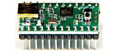
The third robot used this platform.
The control board for the boy's robots is the DFRobot Romeo. This is an Arduino-based board designed with robotics in mind. It has 3-pin headers for every I/O port providing VCC, GND, and signal pins allowing sensors to be easily connected via 3-wire servo cables. There is an on-board motor driver for a pair of motors, a series of buttons, and a socket for an X-bee module. These bots have an LCD display with an I2C interface to save on pins.
 I was using a custom-made motherboard with sockets for the microcontroller board, the LCD panel, the motor driver board, some buttons, and some pin headers for the spare I/O pins. The motor driver I used was the Sparkfun Motor Driver 1A Dual TB6612FNG sourced via Mindkits. The microcontroller is the Teensy, again through Mindkits. This is an AVR board with high compatibility with the Arduino but with several improvements.

We were all running stereo ultra-sonic ranging sonar for can location. These are similar to a Ping))) and require a single digital pin. They return a pulse length for distance to the closest object detected. More complex sonars have the ability to return multiple target distances but we went with what we had. The challenge was balancing the desire to scan across the entire table against detecting objects near the table (like people).
 We all developed similar "arms" in the front of the robot to corral the cans and allow them to be pushed off the table. Our arms could hold a can where the sonar couldn't detect them so we added some proximity sensors to detect the presence of a can. We had some I/R proximity sensors (some robbed from Ernie) so we employed these and they worked really well. The in-built LED indication and the internal pot adjustment allowed calibration without programming.
You might notice my robot had some wires across the back of the arms. This was a last-minute bodge as the edge-avoidance code wasn't properly tuned to allow the robot to tip the can off the edge of the table when it was being held so far back.
 For table detection the boys were using some analog sensors from Pololu (via Mindkits), that we had bought earlier with the intention of doing some line-following. I foolishly thought we had more of them than we did and left my ordering too late to allow for international shipping. Fortunately Mindkits had some Optical Detector-Phototransistor-QRD1114 (the through-hole equivalent part used on the Pololu board) in stock and I made some boards using a couple of resistors and they worked well.
I was also using the circuit board out of an old PS2 ball mouse for reporting wheel encoder counts and button clicks for my LCD menu navigation. The encoder assemblies were removed from the mouse and hot-glued onto the robot but I did not get encoders working for the comp. I suspect I might have something not well aligned but ran out of time to troubleshoot. The advantage of the PS2 mouse is that you don't need interrupt routines in the main micro as the PS2 mouse can be queried for cumulative and current encoder counts together with status of up to 3 buttons.
All of our source code was based on a behaviour subsumption engine that Ben and I wrote a while back which we branched for each robot. Ben coded all behaviours etc himself, Luke specified the psuedo-code with me writing most of the C code for him and Ben helping him to tune it. Luke's next task is to learn C programming properly and take over his own coding.
The next competition will be more of a challenge. The table will be rectangular so we will need to reposition our edge detectors and avoid/ escape behaviours to allow us to get into the corners and out again in case there is a can there. Details are yet to be finalised but we may have to get the cans into a goal instead of simply tipping them off the edge. That would require can capture rather than simply knocking them off the edge.
 |
| Luke's Robot |
 |
| Ben's Robot |
 |
| My robot |
All three robots had two-wheel differential drive chassis from a variety of sources. Two of the bots used cheap motors and wheels from DFRobot attached to home-made bases made from aluminium sheet or from thin MDF.
The third robot used this platform.
I was using a custom-made motherboard with sockets for the microcontroller board, the LCD panel, the motor driver board, some buttons, and some pin headers for the spare I/O pins. The motor driver I used was the Sparkfun Motor Driver 1A Dual TB6612FNG sourced via Mindkits. The microcontroller is the Teensy, again through Mindkits. This is an AVR board with high compatibility with the Arduino but with several improvements.We were all running stereo ultra-sonic ranging sonar for can location. These are similar to a Ping))) and require a single digital pin. They return a pulse length for distance to the closest object detected. More complex sonars have the ability to return multiple target distances but we went with what we had. The challenge was balancing the desire to scan across the entire table against detecting objects near the table (like people).
We all developed similar "arms" in the front of the robot to corral the cans and allow them to be pushed off the table. Our arms could hold a can where the sonar couldn't detect them so we added some proximity sensors to detect the presence of a can. We had some I/R proximity sensors (some robbed from Ernie) so we employed these and they worked really well. The in-built LED indication and the internal pot adjustment allowed calibration without programming.You might notice my robot had some wires across the back of the arms. This was a last-minute bodge as the edge-avoidance code wasn't properly tuned to allow the robot to tip the can off the edge of the table when it was being held so far back.
For table detection the boys were using some analog sensors from Pololu (via Mindkits), that we had bought earlier with the intention of doing some line-following. I foolishly thought we had more of them than we did and left my ordering too late to allow for international shipping. Fortunately Mindkits had some Optical Detector-Phototransistor-QRD1114 (the through-hole equivalent part used on the Pololu board) in stock and I made some boards using a couple of resistors and they worked well.I was also using the circuit board out of an old PS2 ball mouse for reporting wheel encoder counts and button clicks for my LCD menu navigation. The encoder assemblies were removed from the mouse and hot-glued onto the robot but I did not get encoders working for the comp. I suspect I might have something not well aligned but ran out of time to troubleshoot. The advantage of the PS2 mouse is that you don't need interrupt routines in the main micro as the PS2 mouse can be queried for cumulative and current encoder counts together with status of up to 3 buttons.
All of our source code was based on a behaviour subsumption engine that Ben and I wrote a while back which we branched for each robot. Ben coded all behaviours etc himself, Luke specified the psuedo-code with me writing most of the C code for him and Ben helping him to tune it. Luke's next task is to learn C programming properly and take over his own coding.
The next competition will be more of a challenge. The table will be rectangular so we will need to reposition our edge detectors and avoid/ escape behaviours to allow us to get into the corners and out again in case there is a can there. Details are yet to be finalised but we may have to get the cans into a goal instead of simply tipping them off the edge. That would require can capture rather than simply knocking them off the edge.
02 May 2012
RoboNZ Tabletop Competition
It has been quite a long time since my last post - one of my excuses is that I have been busy preparing robots for the Tabletop robotics competition run by our local robotics group last weekend. The competition was founded by Gary, hosted by RoboNZ, and a prize supplied by our friendly robotics supplier Mindkits.
The competition involves an autonomous robot clearing five empty softdrink cans from a 1.2m diameter table in the shortest time. There is a size limit and a time limit. Last weekend was the first competition meet, and after a successful challenge we will be stepping up the complexity each time. Current rules here.
The next few posts will provide details of the robots fielded by the Electronic Kiwi team. There's some footage of the competition on You Tube.
20 January 2012
PS3 joystick progress report
Hooking up the PS3 Joystick and getting some meaningful results on the screen was a lot easier than expected. I purchased a small USB Bluetooth dongle which worked with Ubuntu straight away, and hooking up the software to display the output from the joystick was easy.
Developing a ROS node to convert that output into ROS command messages was also very easy following the tutorial on ros.org; as was my first go at getting a ros launch file setup. Getting the joystick connected requires root privileges and I haven't worked out how to do that bit from within the launch file yet.
My PC (running ROS on Ubuntu) talks to the robot hardware via an Arduino Mega over a USB serial data link. Before switching to ROS I had developed my own serial protocol but lately I have been using the rosserial library which makes writing the Arduino end and the PC end pretty simple. Using this system I was easily able to have the PS3 joystick remotely control the speed and direction of each drive wheel, and the pan and tilt of the head.
The only issue I currently have is that the serial connection keeps on dropping out, and that appears to be a result of the serial link getting swamped with too much data. I have a ROS throttle node running on the PC to limit the rate at which messages are sent to the Arduino but I still haven't got this running properly. More investigation is required. I'll try slowing everything down further, and changing the baud rate. My main worry is that I have so far only implemented a small proportion of the features my Arduino will be handling, so have a lot more data I need to send.
I may need to delve into the rosserial messaging system and see how compact the serial data is - perhaps I'll need to modify the protocol. This is one of the big advantages of ROS over MRDS which I trialled earlier - the system is open-source, so while my C++ and Python skills are pretty basic I can at least look at the source code and potentially modify it.
18 January 2012
A look at Ernie
As promised last year I have taken an up-to-date photo of Ernie, and I'll provide a brief description of his main features. In this photo Ernie's panels have been removed so you can see inside.

Ernie is a large robot for a hobby robot. He is about 0.5m x 0.5m and about 1m tall. As I said in an earlier post he is heavily influenced by Dave Shinsel's Loki robot. I guess he would be a similar size to Loki and to the Astromec droids built by members of the R2D2 builders club.
The size of the base is largely determined by the size of the drivewheels (0.3m diameter) and the drivetrain. Ernie is driven by old cordless drill motors with a chain drive. The chains are off-the-shelf from minature motorcycles and rather than try and shorten them they are used as-is. The wheels and chain are under the side "fenders" to protect anyone coming in contact with the chain. The motors mounted at the rear about halfway up.
The height of the robot is largely determined by the desire to eventually mount arms similar to Loki at the top of the body, and then the height of the head.
The head is a temporary one (made from an old icecream container) with DFRobot LED rings for eyes and an LED VU meter as a mouth (plugged into PC soundcard output). The mouth works but I don't have the progamming sorted for the eyes yet. The head is mounted on two servo motors so it can pan and tilt. The hat was added by one of my sons and I think I'll keep it.
Working down from the head you can see the emergency stop button at the rear of the top panel. This switch cuts all power to the motors and I consider this essential for a robot of this size and weight. Ernie currently weighs about 20kg and he doesn't yet have arms.
Just below the top of the robot at the front is a LED matrix I built. This matrix is 24 x 8 pixels with red and green colours and displays a pattern sent serially from the Arduino. I haven't got this working again since shifting to ROS - only because I haven't got around to it, but I'm now wondering if this display should have it's own Arduino communicating via I2C with the main micro, or by USB directly with the PC given the amount of data I want to shift and the limits of the rosserial comms (more on that in a later post).
Moving on down there are some PC speakers in the middle of the body. On the rear shelf you may be able to see the two Robot Power Simple H motor drivers (with fans) that drive the motors with commands coming from the Arduino.
The main shelf has the Arduino Mega mounted in the centre and some data distribution boards I made. Those boards have 16-way IDC ribbon cables running from near the Arduino to four similar boards elsewhere on the robot. Each one then breaks out the data lines to headers that can be jumpered to the relevant pin on the Arduino and connected to sensors or actuators at the other end.
Below the main shelf is the PC in a small case. The blank space below that has the main axle running through it and I plan to mount the Power Management board in that space with charging contacts and also a line-follower.
I have a number of ultrasonic distance measuring sensors distributed around the front and some simple bumpers.
What you can't see are the quadurature encoders driven by small wheels in contact with the chain, some simple infrared presence detectors as "bumpers" at the rear, and the batteries. I have two fairly large 12v SLA batteries sitting behind the main axle. On the back I have a panel with a number of switches and sockets for external power and charging. Once the power management board is in that panel should get simplified significantly.
After working on this robot for about two years now I'd change some things if I was rebuilding. Firstly I'd like to cut down the weight. At 20kg this robot is difficult to lift on and off the workbench but more importantly it can be quite dangerous moving around people. I'd also try and make it more compact, probably by using slightly smaller wheels and a more compact drive system. Perhaps a couple of wheelchair motors with wheels rather than my current golf-trundler wheels and chain drive.
09 January 2012
Ernie's Christmas
Christmas was kind to Ernie.
He received a new mini-box M3 power supply, a mini-box Y-PWR adapter, and a Playstation PS3 controller.
The M3 power supply is for his on-board PC and is a small unit that fits entirely within the small PC case so less room is required within the body. It also allows the original case lid to be put back on instead of a custom-made one. The M3 power supply is superior to the previous 12v ATX power supply I was using as it generates a proper 12v supply rail, even when the battery supply voltage is below 12v. The CPU is now running significantly cooler - probably due to the perforated case lid, but possibly also due to the cleaner and more accurate voltage supply.
The Y-PWR board is a simple ideal diode that can allow practically instant switching from the battery supply to the external supply for the PC power supply - this is the sort of "switch" that is used in a UPS so that the power can be switched without interupting the operation of the PC. This will be integrated into a new power-management system I am designing that will look after the charging of the two SLA (sealed-lead-acid) batteries in Ernie as well as monitoring battery voltages and switching various circuit groups on and off.
The PS3 controller is wireless via Bluetooth and with the addition of a small USB Bluetooth dongle Ernie should be able to be remotely controlled. This will be useful when transporting Ernie, or demonstrating him and using him as an entertainment robot - part of his intended function. There is a ROS package for the controller and patching it into the ROS system on Ernie is apparently fairly simple.
Subscribe to:
Posts (Atom)