Hooking up the PS3 Joystick and getting some meaningful results on the screen was a lot easier than expected. I purchased a small USB Bluetooth dongle which worked with Ubuntu straight away, and hooking up the software to display the output from the joystick was easy.
Developing a ROS node to convert that output into ROS command messages was also very easy following the tutorial on ros.org; as was my first go at getting a ros launch file setup. Getting the joystick connected requires root privileges and I haven't worked out how to do that bit from within the launch file yet.
My PC (running ROS on Ubuntu) talks to the robot hardware via an Arduino Mega over a USB serial data link. Before switching to ROS I had developed my own serial protocol but
lately I have been using the rosserial library which makes writing the
Arduino end and the PC end pretty simple. Using this system I was easily able to have the PS3 joystick remotely
control the speed and direction of each drive wheel, and the pan and
tilt of the head.
The only issue I currently have is that the serial connection keeps on dropping out, and that appears to be a result of the serial link getting swamped with too much data. I have a ROS throttle node running on the PC to limit the rate at which messages are sent to the Arduino but I still haven't got this running properly. More investigation is required. I'll try slowing everything down further, and changing the baud rate. My main worry is that I have so far only implemented a small proportion of the features my Arduino will be handling, so have a lot more data I need to send.
I may need to delve into the rosserial messaging system and see how compact the serial data is - perhaps I'll need to modify the protocol. This is one of the big advantages of ROS over MRDS which I trialled earlier - the system is open-source, so while my C++ and Python skills are pretty basic I can at least look at the source code and potentially modify it.

20 January 2012

18 January 2012
A look at Ernie
As promised last year I have taken an up-to-date photo of Ernie, and I'll provide a brief description of his main features. In this photo Ernie's panels have been removed so you can see inside.

Ernie is a large robot for a hobby robot. He is about 0.5m x 0.5m and about 1m tall. As I said in an earlier post he is heavily influenced by Dave Shinsel's Loki robot. I guess he would be a similar size to Loki and to the Astromec droids built by members of the R2D2 builders club.
The size of the base is largely determined by the size of the drivewheels (0.3m diameter) and the drivetrain. Ernie is driven by old cordless drill motors with a chain drive. The chains are off-the-shelf from minature motorcycles and rather than try and shorten them they are used as-is. The wheels and chain are under the side "fenders" to protect anyone coming in contact with the chain. The motors mounted at the rear about halfway up.
The height of the robot is largely determined by the desire to eventually mount arms similar to Loki at the top of the body, and then the height of the head.
The head is a temporary one (made from an old icecream container) with DFRobot LED rings for eyes and an LED VU meter as a mouth (plugged into PC soundcard output). The mouth works but I don't have the progamming sorted for the eyes yet. The head is mounted on two servo motors so it can pan and tilt. The hat was added by one of my sons and I think I'll keep it.
Working down from the head you can see the emergency stop button at the rear of the top panel. This switch cuts all power to the motors and I consider this essential for a robot of this size and weight. Ernie currently weighs about 20kg and he doesn't yet have arms.
Just below the top of the robot at the front is a LED matrix I built. This matrix is 24 x 8 pixels with red and green colours and displays a pattern sent serially from the Arduino. I haven't got this working again since shifting to ROS - only because I haven't got around to it, but I'm now wondering if this display should have it's own Arduino communicating via I2C with the main micro, or by USB directly with the PC given the amount of data I want to shift and the limits of the rosserial comms (more on that in a later post).
Moving on down there are some PC speakers in the middle of the body. On the rear shelf you may be able to see the two Robot Power Simple H motor drivers (with fans) that drive the motors with commands coming from the Arduino.
The main shelf has the Arduino Mega mounted in the centre and some data distribution boards I made. Those boards have 16-way IDC ribbon cables running from near the Arduino to four similar boards elsewhere on the robot. Each one then breaks out the data lines to headers that can be jumpered to the relevant pin on the Arduino and connected to sensors or actuators at the other end.
Below the main shelf is the PC in a small case. The blank space below that has the main axle running through it and I plan to mount the Power Management board in that space with charging contacts and also a line-follower.
I have a number of ultrasonic distance measuring sensors distributed around the front and some simple bumpers.
What you can't see are the quadurature encoders driven by small wheels in contact with the chain, some simple infrared presence detectors as "bumpers" at the rear, and the batteries. I have two fairly large 12v SLA batteries sitting behind the main axle. On the back I have a panel with a number of switches and sockets for external power and charging. Once the power management board is in that panel should get simplified significantly.
After working on this robot for about two years now I'd change some things if I was rebuilding. Firstly I'd like to cut down the weight. At 20kg this robot is difficult to lift on and off the workbench but more importantly it can be quite dangerous moving around people. I'd also try and make it more compact, probably by using slightly smaller wheels and a more compact drive system. Perhaps a couple of wheelchair motors with wheels rather than my current golf-trundler wheels and chain drive.

Ernie is a large robot for a hobby robot. He is about 0.5m x 0.5m and about 1m tall. As I said in an earlier post he is heavily influenced by Dave Shinsel's Loki robot. I guess he would be a similar size to Loki and to the Astromec droids built by members of the R2D2 builders club.
The size of the base is largely determined by the size of the drivewheels (0.3m diameter) and the drivetrain. Ernie is driven by old cordless drill motors with a chain drive. The chains are off-the-shelf from minature motorcycles and rather than try and shorten them they are used as-is. The wheels and chain are under the side "fenders" to protect anyone coming in contact with the chain. The motors mounted at the rear about halfway up.
The height of the robot is largely determined by the desire to eventually mount arms similar to Loki at the top of the body, and then the height of the head.
The head is a temporary one (made from an old icecream container) with DFRobot LED rings for eyes and an LED VU meter as a mouth (plugged into PC soundcard output). The mouth works but I don't have the progamming sorted for the eyes yet. The head is mounted on two servo motors so it can pan and tilt. The hat was added by one of my sons and I think I'll keep it.
Working down from the head you can see the emergency stop button at the rear of the top panel. This switch cuts all power to the motors and I consider this essential for a robot of this size and weight. Ernie currently weighs about 20kg and he doesn't yet have arms.
Just below the top of the robot at the front is a LED matrix I built. This matrix is 24 x 8 pixels with red and green colours and displays a pattern sent serially from the Arduino. I haven't got this working again since shifting to ROS - only because I haven't got around to it, but I'm now wondering if this display should have it's own Arduino communicating via I2C with the main micro, or by USB directly with the PC given the amount of data I want to shift and the limits of the rosserial comms (more on that in a later post).
Moving on down there are some PC speakers in the middle of the body. On the rear shelf you may be able to see the two Robot Power Simple H motor drivers (with fans) that drive the motors with commands coming from the Arduino.
The main shelf has the Arduino Mega mounted in the centre and some data distribution boards I made. Those boards have 16-way IDC ribbon cables running from near the Arduino to four similar boards elsewhere on the robot. Each one then breaks out the data lines to headers that can be jumpered to the relevant pin on the Arduino and connected to sensors or actuators at the other end.
Below the main shelf is the PC in a small case. The blank space below that has the main axle running through it and I plan to mount the Power Management board in that space with charging contacts and also a line-follower.
I have a number of ultrasonic distance measuring sensors distributed around the front and some simple bumpers.
What you can't see are the quadurature encoders driven by small wheels in contact with the chain, some simple infrared presence detectors as "bumpers" at the rear, and the batteries. I have two fairly large 12v SLA batteries sitting behind the main axle. On the back I have a panel with a number of switches and sockets for external power and charging. Once the power management board is in that panel should get simplified significantly.
After working on this robot for about two years now I'd change some things if I was rebuilding. Firstly I'd like to cut down the weight. At 20kg this robot is difficult to lift on and off the workbench but more importantly it can be quite dangerous moving around people. I'd also try and make it more compact, probably by using slightly smaller wheels and a more compact drive system. Perhaps a couple of wheelchair motors with wheels rather than my current golf-trundler wheels and chain drive.
09 January 2012
Ernie's Christmas
Christmas was kind to Ernie.
He received a new mini-box M3 power supply, a mini-box Y-PWR adapter, and a Playstation PS3 controller.
The M3 power supply is for his on-board PC and is a small unit that fits entirely within the small PC case so less room is required within the body. It also allows the original case lid to be put back on instead of a custom-made one. The M3 power supply is superior to the previous 12v ATX power supply I was using as it generates a proper 12v supply rail, even when the battery supply voltage is below 12v. The CPU is now running significantly cooler - probably due to the perforated case lid, but possibly also due to the cleaner and more accurate voltage supply.
The Y-PWR board is a simple ideal diode that can allow practically instant switching from the battery supply to the external supply for the PC power supply - this is the sort of "switch" that is used in a UPS so that the power can be switched without interupting the operation of the PC. This will be integrated into a new power-management system I am designing that will look after the charging of the two SLA (sealed-lead-acid) batteries in Ernie as well as monitoring battery voltages and switching various circuit groups on and off.
The PS3 controller is wireless via Bluetooth and with the addition of a small USB Bluetooth dongle Ernie should be able to be remotely controlled. This will be useful when transporting Ernie, or demonstrating him and using him as an entertainment robot - part of his intended function. There is a ROS package for the controller and patching it into the ROS system on Ernie is apparently fairly simple.
He received a new mini-box M3 power supply, a mini-box Y-PWR adapter, and a Playstation PS3 controller.
The M3 power supply is for his on-board PC and is a small unit that fits entirely within the small PC case so less room is required within the body. It also allows the original case lid to be put back on instead of a custom-made one. The M3 power supply is superior to the previous 12v ATX power supply I was using as it generates a proper 12v supply rail, even when the battery supply voltage is below 12v. The CPU is now running significantly cooler - probably due to the perforated case lid, but possibly also due to the cleaner and more accurate voltage supply.
The Y-PWR board is a simple ideal diode that can allow practically instant switching from the battery supply to the external supply for the PC power supply - this is the sort of "switch" that is used in a UPS so that the power can be switched without interupting the operation of the PC. This will be integrated into a new power-management system I am designing that will look after the charging of the two SLA (sealed-lead-acid) batteries in Ernie as well as monitoring battery voltages and switching various circuit groups on and off.
The PS3 controller is wireless via Bluetooth and with the addition of a small USB Bluetooth dongle Ernie should be able to be remotely controlled. This will be useful when transporting Ernie, or demonstrating him and using him as an entertainment robot - part of his intended function. There is a ROS package for the controller and patching it into the ROS system on Ernie is apparently fairly simple.
15 November 2011
Choosing a platform for starting robotics
I was recently asked by a friend for a recommendation as they wanted to provide a kit to their 13-year old daughter to start into robotics. She has had some experience with a high-school robotics competition team and my friend is knowledgeable about electronics. They wanted a cost-effective set of parts or a kit that would ensure success.
My friend had looked around the Internet and thought the Pololu 3pi robot would be a good starting point, particularly with the mBed expansion board added. I had looked very carefully at the 3pi when evaluating a starting setup for my son and ended up choosing a different system, although the mBed expansion wasn't available then. We ended up purchasing the 4WD Rover kit from DFRobot and I recommended a similar setup to my friend.
When I did my earlier evaluation (in late 2010) I read fairly widely on the internet, browsed the ads in Robot magazine and considered a few options. My shortlist ended up being:
I'll provide a very quick summary of both platforms and some other options together with a listing of the benefits and disbenefits of each option and why I recommended the DFRobot solution. I have to preface this whole discussion with the note that there are a HUGE number of getting started robotics platforms out there, and more are being added all the time. What is best for one person won't be best for another and will depend greatly on what you are thinking of doing with it and what your own skills are.
There are some glaring omissions from this "review", including the very popular Lego NXT system, and the Vex robotics system. These are highly capable "retail" systems and either would provide a good start into robotics. These systems are both expensive, particularly when shipping to New Zealand is considered, and both have limitations on expansion. Both come with pre-made curricula and have great support so would be good options for schools.
Onto the descriptions ...
Pololu 3pi.
This is a great little self-contained robot platform with good documentation and support. Pololu describe it as:
The Pololu 3pi robot is a complete, high-performance mobile platform featuring two micro metal gearmotors, five reflectance sensors, an 8×2 character LCD, a buzzer, and three user pushbuttons, all connected to a C-programmable ATmega328 microcontroller. Capable of speeds exceeding 3 feet per second, 3pi is a great first robot for ambitious beginners and a perfect second robot for those looking to move up from non-programmable or slower beginner robots.
As the robot is controlled by an ATmega328, the same microcontroller used on the very popular open-source Arduino boards, it is apparently possible to use the Arduino IDE and libraries with the Pololu. Additional prototpying circuit-boards are available to add extra decks for expansion.
Pololu have recently added the mBed expansion option for the 3pi platform. With this expansion board the robot becomes the m3pi. This expansion board allows an mBed development board to be used as the primary controller with the ATmega328 acting as a slave controller via serial communications. Pololu offer the ARM mbed NXP LPC1768 Development Board which is a very capable microcontroller. Pololu say ...
Based on the powerful NXP LPC1768 Cortex-M3 processor, which runs at 96 MHz and offers 512 KB flash and 64 KB SRAM, the 32-bit mbed can handily outperform popular 8-bit prototyping platforms like the Arduino and Basic Stamp. The mbed also offers peripherals not typically found on lower-performance prototyping boards, such as ethernet, USB OTG, a 12-bit ADC, a 10-bit DAC for a true analog voltage output, in addition to more common interfaces like serial (UART), SPI, I2C, and CAN.
The expansion board also makes it easy to add wireless communications for the m3pi robot. Get the full details at Pololu
Arduino-based
Anyone unfamiliar with the Arduino platform owes it to themselves to investigate this microcontroller phenomenom starting at www.arduino.cc.

In a nutshell this is an open-hardware development board using the capable AVR series of microcontrollers married with easy-to-learn free IDE programming software. Due to the open-hardware nature a wide range of derivative and clone boards are available at reasonable prices. A wide range of expansion boards (known as Shields) are available. Despite a number of detractors (usually hard-core programmer-types) the platform has gained huge success with artists, tinkerers and hobbyists.
The huge range of freely available software examples, forums, books, and compatible expansion boards and accessories make this an attractive platform for learning about microcontrollers - a key component of hobby robotics.
An Arduino board or clone would need to be married with a motor-driver board (a number of Motor Shield options are available), a few sensors, and a simple chassis with motors and wheels. Again a wide variety of options exist, with this chassis from DFRobot being but one example.
Parts Required:
An Arduino or Clone. Say the Arduino UNO, or TwentyEleven or similar.
A Motor Shield. Say the ArduMoto or similar - enough to power most small motors but check the motor stall current is within limits.
A chassis with motors and wheels or tracks. Either make your own or buy one of many kits.
For those of you reading in New Zealand all of the above is available from MindKits. Those elsewhere may prefer to buy from elsewhere such as Pololu, SparkFun, DFRobot or a huge range of on-line robotics hobby stores.
DFRobot Rover
DFRobot offer a number of small robot solutions including chassis ideal for using with an Arduino, including chassis with tank-tracks, 2 wheels, or 4 wheels. You can see a review of the tracked robot at Robot Magazine.
In addition they offer the Romeo robot controller. This is a circuit board with an Arduino clone in the middle, fully compatible with the Arduino software and expansion shields. Also included on the board are built-in motor drivers for two DC motors, some push buttons, and a range of "headers" to make connecting sensors easy, and a socket for a wireless communication board.
My son chose the DFRobot 4WD chassis. The metal components are well made and durable and he had no trouble in assembling the robot. A small amount of soldering is required to connect up the motors, battery holder and switch.
After some use we ended up needing two replacement motors, and this is my only negative comment about the DFRobot system. The motors have plastic shafts and plastic gears - clearly why they are able to be priced so low. After a few weeks of use we had one motor with a broken gear tooth and another with a broken shaft. The motors are cheap to replace but not particularly durable. I'm not sure that the same problems would have occurred with a 2WD robot as the 4WD skid-steer system places additional loads on the motors when turning the robot and the wheels are near the corners where they are more vunerable to collisions.
 After using the 4WD robot for a while my son realised why most small
robots are round with two drivewheels and a castor - they are far easy
to manoeuvre. We ended up making a small round chassis ourselves from
aluminium sheet. We could have purchased the 2WD chassis from DFRobot
but when shipping was added this was a fairly expensive and we
thought making our own chassis would be fun and educational. We re-used components from the 4WD chassis kit including the two good motors.
After using the 4WD robot for a while my son realised why most small
robots are round with two drivewheels and a castor - they are far easy
to manoeuvre. We ended up making a small round chassis ourselves from
aluminium sheet. We could have purchased the 2WD chassis from DFRobot
but when shipping was added this was a fairly expensive and we
thought making our own chassis would be fun and educational. We re-used components from the 4WD chassis kit including the two good motors.
Now on to the comparison and evaluation ...
I ended up going with the DFRobot Romeo for a number of reasons. At the time the mBed expansion wasn't available, and I'll summarise the impact that has at the end.
1. The 3pi has most Input/ Output (IO) ports tied to on-board peripherals whereas on the romeo you can remove jumpers and free up all the pins. When working with most microcontrollers the first thing you run out of is IO pins. The 3pi has the option of disabling some on-board functions which gives the option of freeing up to 3 digital IO pins and up to 3 free analog-to-digital conversion (ADC) pins.
2. 3pi has no wheel encoders and no apparent way to add them as there are no free interrupt-able IO pins spare. This is not a major for line-following or maze-solving but for other tasks having encoders might be really useful.
3. From what I can tell from the available information there is no end-user access to I2C/TWI or SPI on the 3pi. (These are systems that allow communication between various integrated circuits). On the arduino/Romeo you can add on peripherals using these busses which saves on input pins.
4. If you wanted to upgrade the hardware (bigger platform, bigger motors, servos, an arm) it was going to be difficult with the 3pi, easy with the arduino as we have already proved by abandoning our original 4-wheel chassis for a home-built 2-wheel one. We could build a bigger or smaller robot and keep the controller (and code).
5. If you wanted to upgrade the microcontroller you could keep the chassis, motors etc. For example a Parallax Propeller board or an mBed board would give more power.
6. I am comfortable selecting various components (motors, motor driver boards, sensors) etc and putting them together so an Arduino-based solution is a viable option for me, but in the end the Romeo and the DFRobot system with their sensors and sensor cables make the selection and configuration easy. The 3pi is all done for you.
7. I am comfortable doing basic DIY chassis-building. There are a variety of options including plastic sheet, MDF, aluminium sheet, LEGO, meccano (erector set) or whatever.
8. I am already using the Arduino on other projects so am familiar with it.
For me a big thing was that with the Romeo you essentially get a standard Arduinot which allows the controller board to be used for a whole lot of non-robot applications and get into the other dimensions of microcontrollers and electronics, and the Arduino community is truly enormous. Have a look at http://tronixstuff.wordpress.com/tutorials/ and http://www.arduino.cc.
Anyway, that was my earlier evaluation before the mbed expansion was available. The 3pi is a very good beginner-intermediate robot platform that would require less integration work. At it's core it has the same controller chip as the arduino - the main difference is that it has a pre-built chassis and integrated peripherals - that is both a good thing (easier to use) and a bad one (ties up IO lines). With the 3pi there are few additional lines available for adding extra sensors, but with the Romeo a complete re-configuration for a different task is possible.
m3pi Option
The mBed expansion option to convert the 3pi to the m3pi addresses many of the potential shortcomings with the 3pi - providing access to I2C and SPI busses, access to more IO pins, not to mention more power - but this power comes at significant extra cost.
The Romeo/ Arduino path also allows for expansion via several paths:
If you decide to go with the 3pi I'm sure it will work well and be a good solution, particularly with an mbed available to expand into; but I have found the DFRobot Romeo to be an excellent (and very flexible) platform for beginning roboteers.
My friend had looked around the Internet and thought the Pololu 3pi robot would be a good starting point, particularly with the mBed expansion board added. I had looked very carefully at the 3pi when evaluating a starting setup for my son and ended up choosing a different system, although the mBed expansion wasn't available then. We ended up purchasing the 4WD Rover kit from DFRobot and I recommended a similar setup to my friend.
When I did my earlier evaluation (in late 2010) I read fairly widely on the internet, browsed the ads in Robot magazine and considered a few options. My shortlist ended up being:
- Pololu 3pi Robot.
- An Arduino, a Motor-Shield, and a chassis possibly built from Tamiya parts.
- One of the DFRobot kits using a Romeo controller.
I'll provide a very quick summary of both platforms and some other options together with a listing of the benefits and disbenefits of each option and why I recommended the DFRobot solution. I have to preface this whole discussion with the note that there are a HUGE number of getting started robotics platforms out there, and more are being added all the time. What is best for one person won't be best for another and will depend greatly on what you are thinking of doing with it and what your own skills are.
There are some glaring omissions from this "review", including the very popular Lego NXT system, and the Vex robotics system. These are highly capable "retail" systems and either would provide a good start into robotics. These systems are both expensive, particularly when shipping to New Zealand is considered, and both have limitations on expansion. Both come with pre-made curricula and have great support so would be good options for schools.
Onto the descriptions ...
Pololu 3pi.
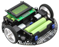 |
| The Pololu 3pi |
The Pololu 3pi robot is a complete, high-performance mobile platform featuring two micro metal gearmotors, five reflectance sensors, an 8×2 character LCD, a buzzer, and three user pushbuttons, all connected to a C-programmable ATmega328 microcontroller. Capable of speeds exceeding 3 feet per second, 3pi is a great first robot for ambitious beginners and a perfect second robot for those looking to move up from non-programmable or slower beginner robots.
As the robot is controlled by an ATmega328, the same microcontroller used on the very popular open-source Arduino boards, it is apparently possible to use the Arduino IDE and libraries with the Pololu. Additional prototpying circuit-boards are available to add extra decks for expansion.
Pololu have recently added the mBed expansion option for the 3pi platform. With this expansion board the robot becomes the m3pi. This expansion board allows an mBed development board to be used as the primary controller with the ATmega328 acting as a slave controller via serial communications. Pololu offer the ARM mbed NXP LPC1768 Development Board which is a very capable microcontroller. Pololu say ...
Based on the powerful NXP LPC1768 Cortex-M3 processor, which runs at 96 MHz and offers 512 KB flash and 64 KB SRAM, the 32-bit mbed can handily outperform popular 8-bit prototyping platforms like the Arduino and Basic Stamp. The mbed also offers peripherals not typically found on lower-performance prototyping boards, such as ethernet, USB OTG, a 12-bit ADC, a 10-bit DAC for a true analog voltage output, in addition to more common interfaces like serial (UART), SPI, I2C, and CAN.
The expansion board also makes it easy to add wireless communications for the m3pi robot. Get the full details at Pololu
Arduino-based
Anyone unfamiliar with the Arduino platform owes it to themselves to investigate this microcontroller phenomenom starting at www.arduino.cc.
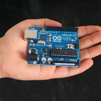
In a nutshell this is an open-hardware development board using the capable AVR series of microcontrollers married with easy-to-learn free IDE programming software. Due to the open-hardware nature a wide range of derivative and clone boards are available at reasonable prices. A wide range of expansion boards (known as Shields) are available. Despite a number of detractors (usually hard-core programmer-types) the platform has gained huge success with artists, tinkerers and hobbyists.
The huge range of freely available software examples, forums, books, and compatible expansion boards and accessories make this an attractive platform for learning about microcontrollers - a key component of hobby robotics.
An Arduino board or clone would need to be married with a motor-driver board (a number of Motor Shield options are available), a few sensors, and a simple chassis with motors and wheels. Again a wide variety of options exist, with this chassis from DFRobot being but one example.
Parts Required:
An Arduino or Clone. Say the Arduino UNO, or TwentyEleven or similar.
A Motor Shield. Say the ArduMoto or similar - enough to power most small motors but check the motor stall current is within limits.
A chassis with motors and wheels or tracks. Either make your own or buy one of many kits.
For those of you reading in New Zealand all of the above is available from MindKits. Those elsewhere may prefer to buy from elsewhere such as Pololu, SparkFun, DFRobot or a huge range of on-line robotics hobby stores.
 |
| A DFRobot miniQ chassis with an Arduino and Motor Shield |
DFRobot Rover
DFRobot offer a number of small robot solutions including chassis ideal for using with an Arduino, including chassis with tank-tracks, 2 wheels, or 4 wheels. You can see a review of the tracked robot at Robot Magazine.
In addition they offer the Romeo robot controller. This is a circuit board with an Arduino clone in the middle, fully compatible with the Arduino software and expansion shields. Also included on the board are built-in motor drivers for two DC motors, some push buttons, and a range of "headers" to make connecting sensors easy, and a socket for a wireless communication board.
 |
| DFRobot 4WD Chassis with Romeo |
After some use we ended up needing two replacement motors, and this is my only negative comment about the DFRobot system. The motors have plastic shafts and plastic gears - clearly why they are able to be priced so low. After a few weeks of use we had one motor with a broken gear tooth and another with a broken shaft. The motors are cheap to replace but not particularly durable. I'm not sure that the same problems would have occurred with a 2WD robot as the 4WD skid-steer system places additional loads on the motors when turning the robot and the wheels are near the corners where they are more vunerable to collisions.
Now on to the comparison and evaluation ...
I ended up going with the DFRobot Romeo for a number of reasons. At the time the mBed expansion wasn't available, and I'll summarise the impact that has at the end.
1. The 3pi has most Input/ Output (IO) ports tied to on-board peripherals whereas on the romeo you can remove jumpers and free up all the pins. When working with most microcontrollers the first thing you run out of is IO pins. The 3pi has the option of disabling some on-board functions which gives the option of freeing up to 3 digital IO pins and up to 3 free analog-to-digital conversion (ADC) pins.
2. 3pi has no wheel encoders and no apparent way to add them as there are no free interrupt-able IO pins spare. This is not a major for line-following or maze-solving but for other tasks having encoders might be really useful.
3. From what I can tell from the available information there is no end-user access to I2C/TWI or SPI on the 3pi. (These are systems that allow communication between various integrated circuits). On the arduino/Romeo you can add on peripherals using these busses which saves on input pins.
4. If you wanted to upgrade the hardware (bigger platform, bigger motors, servos, an arm) it was going to be difficult with the 3pi, easy with the arduino as we have already proved by abandoning our original 4-wheel chassis for a home-built 2-wheel one. We could build a bigger or smaller robot and keep the controller (and code).
5. If you wanted to upgrade the microcontroller you could keep the chassis, motors etc. For example a Parallax Propeller board or an mBed board would give more power.
6. I am comfortable selecting various components (motors, motor driver boards, sensors) etc and putting them together so an Arduino-based solution is a viable option for me, but in the end the Romeo and the DFRobot system with their sensors and sensor cables make the selection and configuration easy. The 3pi is all done for you.
7. I am comfortable doing basic DIY chassis-building. There are a variety of options including plastic sheet, MDF, aluminium sheet, LEGO, meccano (erector set) or whatever.
8. I am already using the Arduino on other projects so am familiar with it.
For me a big thing was that with the Romeo you essentially get a standard Arduinot which allows the controller board to be used for a whole lot of non-robot applications and get into the other dimensions of microcontrollers and electronics, and the Arduino community is truly enormous. Have a look at http://tronixstuff.wordpress.com/tutorials/ and http://www.arduino.cc.
Anyway, that was my earlier evaluation before the mbed expansion was available. The 3pi is a very good beginner-intermediate robot platform that would require less integration work. At it's core it has the same controller chip as the arduino - the main difference is that it has a pre-built chassis and integrated peripherals - that is both a good thing (easier to use) and a bad one (ties up IO lines). With the 3pi there are few additional lines available for adding extra sensors, but with the Romeo a complete re-configuration for a different task is possible.
m3pi Option
The mBed expansion option to convert the 3pi to the m3pi addresses many of the potential shortcomings with the 3pi - providing access to I2C and SPI busses, access to more IO pins, not to mention more power - but this power comes at significant extra cost.
The Romeo/ Arduino path also allows for expansion via several paths:
- swapping the basic Arduino for a more powerful one (eg Arduino Mega) but this would require a replacement motor driver.
- Swapping out the Arduino controller for a different more powerful controller such as a Propellor or mBed.
- adding on a second controller in a similar manner to the mBed expansion, either via a custom solution, perhaps built on a prototyping shield. Another option is the Propelleruino which has a Parallax Propeller chip on an expansion shield.
If you decide to go with the 3pi I'm sure it will work well and be a good solution, particularly with an mbed available to expand into; but I have found the DFRobot Romeo to be an excellent (and very flexible) platform for beginning roboteers.
30 October 2011
Introducing Ernie
My most significant current project is Ernie, and I'll be writing quite a bit about him here.
The name is an extension of ERN-E, or Enhanced Robotic Navigator - Experimental, but I have found Ernie simpler to type.
Inspiration
Ernie is a relatively large robot for a hobby robot. My design of Ernie is very heavily influenced by Loki created by Dave Shinsel, with other robots also influencing some of my thinking including Pi robot created by Patrick Goebel, and more recently Michael Ferguson's Maxwell. I also took an interest in Leaf at one point.
Purpose
One of the first things many people ask is "What does it do?" or "What is it for?". That's a reasonable question without a particularly satisfactory answer. Ernie is sort of an answer looking for a solution - he is an outlet for my hobby interests - an experimental platform. My wife would like Ernie to be able to perform some useful household tasks, but unfortunately her wishlist has more to do with popula television science-fiction than tasks currently achievable by any actual robot, let alone one built on a hobby budget.
I'm intending that Ernie be interesting and entertaining. This is why Ernie will have an expressive face and will have the ability to be steered by remote control. In this I am influenced and impressed by the people that build replica R2-D2 and other astromech droids and by their friends that build replicas of Wall-E.
I hope that he will eventually be capable of tracking a face via a webcam and engage in a semi-intelligent conversation through the merging of a speech-recognition module, a chatbot engine, and a text-to-speech module. I'm also hoping that I will be able to voice-command Ernie to travel from one room to another autonomously.
In coming posts I'll cover some of the construction of Ernie including my selection of motors, drivetrain, and chassis. I plan to describe the circuitry and processors on board, and the software that will run on him. This will include some discussion of programming languages and environments that I have considered and what I am currently using.
 This is an early photo of Ernie. I recycled some cardboard boxes to mock-up a chassis and skin for Ernie to check placements for components such as an LCD panel, arms, drive wheels, an omni-vision system for navigation and a web-cam mounted on a pan-tilt head.
I have since made quite a few changes, but regretably have not been taking too many photos along the way, so I need to start taking images of Ernie as he is currently.
More to come....
The name is an extension of ERN-E, or Enhanced Robotic Navigator - Experimental, but I have found Ernie simpler to type.
Inspiration
Ernie is a relatively large robot for a hobby robot. My design of Ernie is very heavily influenced by Loki created by Dave Shinsel, with other robots also influencing some of my thinking including Pi robot created by Patrick Goebel, and more recently Michael Ferguson's Maxwell. I also took an interest in Leaf at one point.
Purpose
One of the first things many people ask is "What does it do?" or "What is it for?". That's a reasonable question without a particularly satisfactory answer. Ernie is sort of an answer looking for a solution - he is an outlet for my hobby interests - an experimental platform. My wife would like Ernie to be able to perform some useful household tasks, but unfortunately her wishlist has more to do with popula television science-fiction than tasks currently achievable by any actual robot, let alone one built on a hobby budget.
I'm intending that Ernie be interesting and entertaining. This is why Ernie will have an expressive face and will have the ability to be steered by remote control. In this I am influenced and impressed by the people that build replica R2-D2 and other astromech droids and by their friends that build replicas of Wall-E.
I hope that he will eventually be capable of tracking a face via a webcam and engage in a semi-intelligent conversation through the merging of a speech-recognition module, a chatbot engine, and a text-to-speech module. I'm also hoping that I will be able to voice-command Ernie to travel from one room to another autonomously.
In coming posts I'll cover some of the construction of Ernie including my selection of motors, drivetrain, and chassis. I plan to describe the circuitry and processors on board, and the software that will run on him. This will include some discussion of programming languages and environments that I have considered and what I am currently using.

I have since made quite a few changes, but regretably have not been taking too many photos along the way, so I need to start taking images of Ernie as he is currently.
More to come....
Inaugural Post
Welcome to The Electronic Kiwi.
This is a blog about technology - mostly hobby robotics.
I'm a Kiwi - a New Zealander - living in Auckland, New Zealand. I'll be blogging about the robotic and other technology projects I am working on, robots by friends and family, reviews of books and products, cool robotic projects and happenings from around the world, and other assorted stuff.
I've been a professional sofware developer and interested in electronics and robotics for quite a few years. I have assisted with a school Vex competition team and I am currently developing some robotic projects at home together with my children and friends.
This is a blog about technology - mostly hobby robotics.
I'm a Kiwi - a New Zealander - living in Auckland, New Zealand. I'll be blogging about the robotic and other technology projects I am working on, robots by friends and family, reviews of books and products, cool robotic projects and happenings from around the world, and other assorted stuff.
I've been a professional sofware developer and interested in electronics and robotics for quite a few years. I have assisted with a school Vex competition team and I am currently developing some robotic projects at home together with my children and friends.
Subscribe to:
Posts (Atom)